
Basic tutorial on how to install, and remove the Talon hardtop locking system.
Read MoreNB Multipurpose Accessory Panel

NA8 Tombstone Vent Bezel Installation

NA6 Tombstone Vent Bezel Installation

LED Holder + resistor install

S2K Starter Button Wiring Diagram

NA Map Light Installation Document
Removal of the factory NA6 OEM map lights
Unscrew and remove the glovebox, and steering column shield to gain more working room.
Unplug the original map light from the harness, and pop it out. The map light is held on by a clip on either side.
Do the same for the driver’s side factory map light.
Removal of the factory NA8 OEM map light
Unscrew glove box to gain more working room.
Unplug the original map light from the harness, and pop it out. The map light is held on by a clip on either side.
Installation of the RM Map Light upgrade kit
Taking the back mounting bezel assembly (this is the panel with the LED, and various toggle[s]), place it behind the dash, and plug it into the factory harness (this is where removing the glovebox is crucial towards ease of access).
Position the back mounting bezel on the backside of the dash where the original map light opening is located. Note: This bezel should be located behind the dash.
Place the front bezel into the recessed hole where the original map light used to reside.
Line up the 4 mounting corner holes and insert a provided M3 machined screw into each hole.
Hand tighten until it is snug. It should not be any more than 2-3 ft lbs at most.
WARNING: DO NOT OVER-TORQUE THE SCREWS!!
STRIPPED THREADS ARE NOT COVERED UNDER WARRANTY.Foot Well Light Stand-Alone Wiring
NA & NB stand alone hard wire instructions.
NA/NB Miata Wiring Instruction:
You will need to identify two wires in order for this to work; a main power (+12v), and the door trigger wire.
NA (1989-1997) - Look for the factory Map/Knee Light harness (shown below) and identify the Red (+12v) and the White (door trigger) wires. Using the supplied in-line connectors, attach the Red wire from the RM Foot Well harness to the Red wire of the factory harness. Connect the Black wire from the RM Foot Well harness to the White wire of the factory harness.
NB (1999-2005) - Run a set of wires (two wires of different color) from the Foot Well lights over to the driver’s side kick panel.
You will need to disassemble the kick panel and look for a White w/ Red stripe wire. This is your door trigger, and will provide the necessary ground signal.
Look for the factory radio harness, and identify the BLUE/RED wire. This is your main +12v to your Foot Well Lights. Connect the Red wire from the Foot Well Light harness to this wire.
Note: If you already own the RM Map Light Kit for NA Miata, just plug the Foot Well light directly into the red color plug coming off the back of the Map Light harness.


NA Pop-up & Hazard Toggle Switch Assembly Wiring Diagram
NB Power Window Install & Wiring Diagram

US Driver Down: White/Red
US Driver Up: Green/Red
US Passenger Down: Red/Green
US Passenger Up: Red/Black
+12v Constant Power: Brown
Ground: Black
NA POWER WINDOW WIRING DIAGRAM
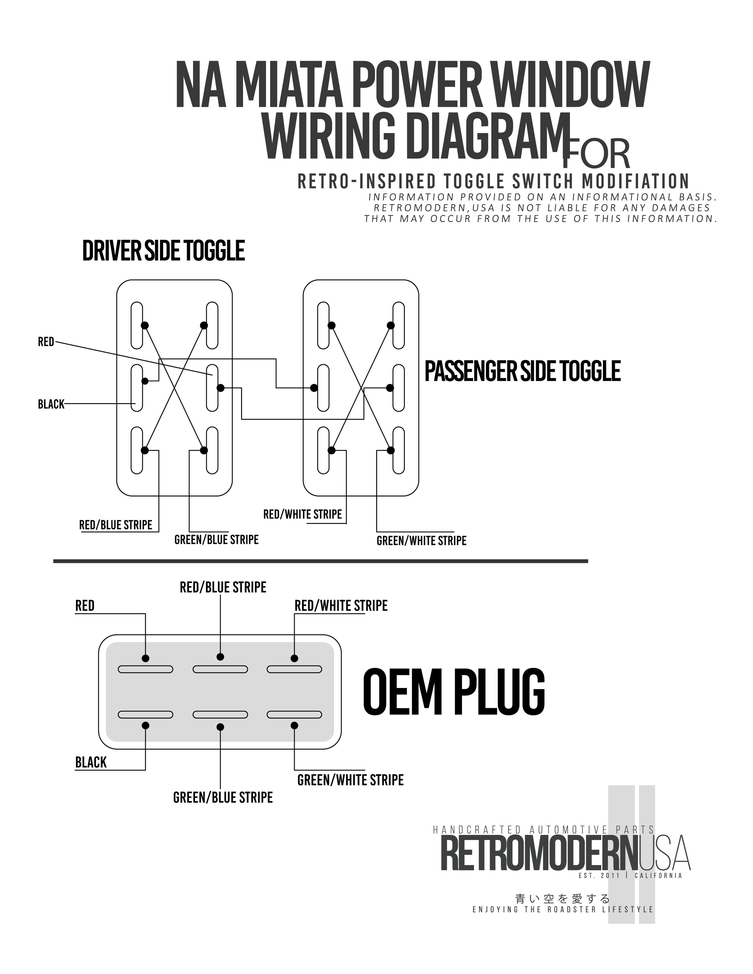

US Driver Open: Green/White:
US Driver Close: Red/White
US Passenger Open: Green/Blue
US Passenger Close: Red/Blue
+12v Power: Red
Ground: Black

Current RM, USA logo
RM, USA Company Logo
RetroModern, USA company logos in vector format.
Read More